
Page 510 -
P. 510
15.18 CHAPTER FIFTEEN
Gas Feed Equipment
Chlorine and ammonia gases are used in disinfection treatment processes and require care.
ful selection of equipment because of the aggressiveness and dangers associated with the
gases.
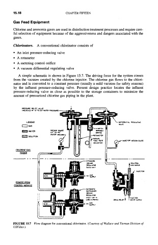
Chlorinators. A conventional chlorinator consists of
• An inlet pressure-reducing valve
• A rotameter
• A metering control orifice
• A vacuum differential regulating valve
A simple schematic is shown in Figure 15.7. The driving force for the system comes
from the vacuum created by the chlorine injector. The chlorine gas flows to the chlori-
nator and is converted to a constant pressure (usually a mild vacuum for safety reasons)
by the influent pressure-reducing valve. Present design practice locates the influent
pressure-reducing valve as close as possible to the storage containers to minimize the
amount of pressurized chlorine gas piping in the plant.
Plq[S.~ua£ nELIEr vALVE
(reEL,IrES *.1" 10" TO 20" WATER
LEGEND
F'--"IGAS
~'~WATER
~SOLUTION
CHLORINE GAS
FEEDER
~..xrc. h l l T =sc..~o,E
CHCCK UNiT ~ ~ ~/ INJ(.CTOR
GAS
5 UlH',.y
REMOTE FROM
CONTROL MODULE
~c
) 0~N ~LEr I wA~[~ ~PLv
FIGURE 15.7 Flow diagram for conventional chlorinator. (Courtesy of Wallace and Tiernan Division of
USFiher.)