
Page 140 - 15 Dangerously Mad Projects for the Evil Genius
P. 140
118 15 Dangerously Mad Projects for the Evil Genius
The first step is to cut a piece of stripboard that
has 12 strips, each with 12 holes. Five breaks must
then be made in the tracks. Make these using a
drill bit—that is, just using it as a hand tool and
rotating it between your finger and thumb. Figure
9-17 shows the prepared board ready to have the
components soldered to it.
Step 2. Solder the Links
and Resistors
Before starting on the real components, solder the
six wire links into place (Figure 9-18). Note that
you will need to bend some of the links to fit them
all on the board.
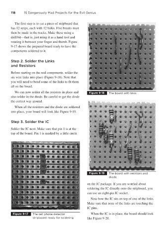
We can now solder all the resistors in place and Figure 9-18 The board with links
also solder in the diode. Be careful to get the diode
the correct way around.
When all the resistors and the diode are soldered
into place, your board will look like Figure 9-19.
Step 3. Solder the IC
Solder the IC next. Make sure that pin 1 is at the
top of the board. Pin 1 is marked by a little circle
Figure 9-19 The board with resistors and
diode
on the IC package. If you are worried about
soldering the IC directly onto the stripboard, you
can use an eight-pin IC socket.
Note how the IC sits on top of one of the links.
Make sure that none of the links are touching the
IC pins.
Figure 9-17 The cell phone detector When the IC is in place, the board should look
stripboard ready for soldering like Figure 9-20.