
Page 141 - 15 Dangerously Mad Projects for the Evil Genius
P. 141
Chapter 9 ■ Covert Radio Bug 119
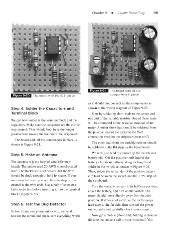
Figure 9-21 The board with all the
Figure 9-20 The board with the IC in place components in place
as it should. So, connect up the components as
Step 4. Solder the Capacitors and shown in the wiring diagram of Figure 9-23.
Terminal Block Start by soldering short leads to the center and
one end of the variable resistor. One of these leads
We can now solder in the terminal block and the
will be connected to the negative terminal of the
capacitors. Make sure the capacitors are the correct
meter. Another short lead should be soldered from
way around. They should both have the longer
the positive lead of the meter to the Vref
positive lead toward the bottom of the stripboard.
connection track on the stripboard next to C1.
The board with all the components in place is
The other lead from the variable resistor should
shown in Figure 9-21.
be soldered to the R4 strip on the breadboard.
We now just need to connect up the switch and
Step 5. Make an Antenna
battery clip. Cut the positive (red) lead of the
The antenna is just a loop of wire 150mm in battery clip about halfway along its length and
length. The author used 20-AWG enamel-coated solder in the switch, as shown in Figure 9-23.
wire. The thickness is not critical, but the wire Then, solder the remainder of the positive battery
should be thick enough to hold its shape. If you clip lead between the switch and the 9V strip on
use enameled wire, you will have to strip off the the stripboard.
enamel at the wire ends. Use a pair of snips or a
Turn the variable resistor to its halfway position,
knife to do this before inserting it into the terminal
attach the battery, and turn on the switch. The
block (Figure 9-22).
meter should move slightly away from its zero
position. If it does not move, or the meter pings
Step 6. Test the Bug Detector hard over to the far side, then turn off the power
immediately and carefully check your circuit.
Before fixing everything into a box, we need to
test out the circuit and make sure everything works Now get a mobile phone and, holding it close to
the antenna, make a call to your voicemail. You