
Page 234 - 15 Dangerously Mad Projects for the Evil Genius
P. 234
Appendix ■ Electronics Construction Primer 209
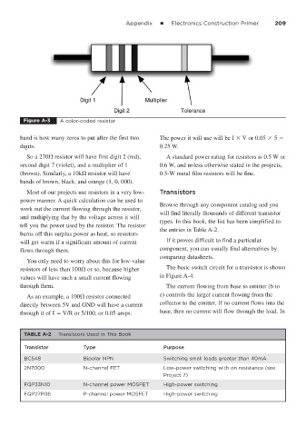
Figure A-3 A color-coded resistor
band is how many zeros to put after the first two The power it will use will be I V or 0.05 5
digits. 0.25 W.
So a 270 resistor will have first digit 2 (red), A standard power rating for resistors is 0.5 W or
second digit 7 (violet), and a multiplier of 1 0.6 W, and unless otherwise stated in the projects,
(brown). Similarly, a 10k resistor will have 0.5-W metal film resistors will be fine.
bands of brown, black, and orange (1, 0, 000).
Most of our projects use resistors in a very low- Transistors
power manner. A quick calculation can be used to
Browse through any component catalog and you
work out the current flowing through the resistor,
will find literally thousands of different transistor
and multiplying that by the voltage across it will
types. In this book, the list has been simplified to
tell you the power used by the resistor. The resistor
the entries in Table A-2.
burns off this surplus power as heat, so resistors
will get warm if a significant amount of current If it proves difficult to find a particular
flows through them. component, you can usually find alternatives by
comparing datasheets.
You only need to worry about this for low-value
resistors of less than 100 or so, because higher The basic switch circuit for a transistor is shown
values will have such a small current flowing in Figure A-4.
through them. The current flowing from base to emitter (b to
As an example, a 100 resistor connected e) controls the larger current flowing from the
directly between 5V and GND will have a current collector to the emitter. If no current flows into the
through it of I V/R or 5/100, or 0.05 amps. base, then no current will flow through the load. In
TABLE A-2 Transistors Used in This Book
Transistor Type Purpose
BC548 Bipolar NPN Switching small loads greater than 40mA
2N7000 N-channel FET Low-power switching with on resistance (see
Project 7)
FQP33N10 N-channel power MOSFET High-power switching
FQP27P06 P-channel power MOSFET High-power switching