Page 235 - 15 Dangerously Mad Projects for the Evil Genius
P. 235

210       15 Dangerously Mad Projects for the Evil Genius


                                            +V             of about 0.6V between the base and emitter when a
                                                           transistor is turned on.

                                                             Using a 150  base resistor, we could therefore
                                                           control a collector current of 40 to 200 times
                                                           30mA, or 1.2A to 6A, which is more than enough
                                                           for most purposes.

                                                             In practice, we would probably use a resistor of
                                                 LOAD
                                                           1k , or perhaps 270 .
                                                             Transistors have a number of maximum
                                                           parameter values that should not be exceeded,
                                                           otherwise the transistor may be damaged. You can
                                                           find these by looking at the datasheet for the
                                                           transistor.
                                                   c
                                                             For example, the datasheet for a BC548 will
                                       b
                                                           contain many values. The ones of most interest to
                           Rb
                                                           us are summarized in Table A-3.
                                                   e
                                                            TABLE A-3   Transistor Datasheet

            GND                                             Property   Value    What It Means
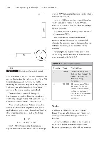
         Figure A-4    Basic transistor switch circuit
                                                            I c        100mA    The maximum current
                                                                                that can flow through the
        most transistors, if the load has zero resistance, the                  collector without the
        current flowing into the collector will be 50 to 200                    transistor being
                                                                                damaged.
        times the base current. However, we will be
        switching our transistor fully on or fully off, so the  h FE   110–800 DC current gain. This is
                                                                                the ratio of collector
        load resistance will always limit the collector
                                                                                current to base current,
        current to the current required by the load.
                                                                                and as you can see, it
           Too much base current will damage the                                can be anything between
        transistor and also rather defeat the objective of                      110 and 800 for this
        controlling a bigger current with a smaller one. So,                    transistor.
        the base will have a resistor connected to it.
           When switching from an Arduino board, the
                                                           Diodes
        maximum current of an output is 40mA, so we
        could choose a resistor that allows about 30mA to  In addition to LEDs, there are also “normal”
        flow when the output pin is high at 5V. Using      diodes. These act a bit like one-way valves, only
        Ohm’s law:                                         allowing current to flow through them in one
                           R   V/I                         direction.
                    R   (5 – 0.6)/30   147                   We have used them in a few of the projects in
                                                           this book to prevent unwanted currents from
           The “– 0.6” is because one characteristic of
                                                           damaging components, or when driving inductive
        bipolar transistors is that there is always a voltage
   230   231   232   233   234   235   236   237   238   239   240