
Page 89 - 15 Dangerously Mad Projects for the Evil Genius
P. 89
68 15 Dangerously Mad Projects for the Evil Genius
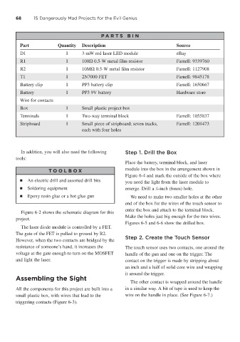
P A RT S BIN
Part Quantity Description Source
D1 1 3-mW red laser LED module eBay
R1 1 100 0.5-W metal film resistor Farnell: 9339760
R2 1 10M 0.5-W metal film resistor Farnell: 1127908
T1 1 2N7000 FET Farnell: 9845178
Battery clip 1 PP3 battery clip Farnell: 1650667
Battery 1 PP3 9V battery Hardware store
Wire for contacts
Box 1 Small plastic project box
Terminals 1 Two-way terminal block Farnell: 1055837
Stripboard 1 Small piece of stripboard; seven tracks, Farnell: 1201473
each with four holes
In addition, you will also need the following Step 1. Drill the Box
tools:
Place the battery, terminal block, and laser
T OOLBO X module into the box in the arrangement shown in
Figure 6-4 and mark the outside of the box where
■ An electric drill and assorted drill bits you need the light from the laser module to
1
■ Soldering equipment emerge. Drill a ⁄4-inch (6mm) hole.
■ Epoxy resin glue or a hot glue gun We need to make two smaller holes at the other
end of the box for the wires of the touch sensor to
enter the box and attach to the terminal block.
Figure 6-2 shows the schematic diagram for this
Make the holes just big enough for the two wires.
project.
Figures 6-5 and 6-6 show the drilled box.
The laser diode module is controlled by a FET.
The gate of the FET is pulled to ground by R2.
Step 2. Create the Touch Sensor
However, when the two contacts are bridged by the
resistance of someone’s hand, it increases the The touch sensor uses two contacts, one around the
voltage at the gate enough to turn on the MOSFET handle of the gun and one on the trigger. The
and light the laser. contact on the trigger is made by stripping about
an inch and a half of solid core wire and wrapping
it around the trigger.
Assembling the Sight
The other contact is wrapped around the handle
All the components for this project are built into a in a similar way. A bit of tape is used to keep the
small plastic box, with wires that lead to the wire on the handle in place. (See Figure 6-7.)
triggering contacts (Figure 6-3).