
Page 91 - 15 Dangerously Mad Projects for the Evil Genius
P. 91
70 15 Dangerously Mad Projects for the Evil Genius
Figure 6-5 The drilled box (front)
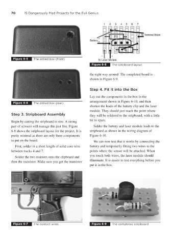
Figure 6-8 The stripboard layout
the right way around. The completed board is
shown in Figure 6-9.
Step 4. Fit It into the Box
Lay out the components in the box in the
arrangement shown in Figure 6-10, and then
Figure 6-6 The drilled box (rear)
shorten the leads of the battery clip and the laser
module. They should just reach the point where
Step 3. Stripboard Assembly they will be soldered to the stripboard, with a little
Begin by cutting the stripboard to size. A strong bit to spare.
pair of scissors will manage this just fine. Figure Solder the battery and laser module leads to the
6-8 shows the stripboard layout for the project. It is stripboard as shown in the wiring diagram of
pretty minimal as there are only three components Figure 6-10.
to put on the board. We can now test that it works by connecting the
First, solder in a short length of solid core wire battery and temporarily fitting two wires to the
between tracks 4 and 7. points where the sensor will be attached. When
you touch both wires, the laser module should
Solder the two resistors onto the clipboard and
illuminate. It is easier to test everything before you
then the transistor. Make sure you get the transistor
put it in the box.
Figure 6-7 The contact wires Figure 6-9 The completed stripboard