
Page 96 - 15 Dangerously Mad Projects for the Evil Genius
P. 96
Chapter 7 ■ Laser-Grid Intruder Alarm 75
design, so we can actually build it without a circuit
T OOLBO X
board.
■ An electric drill and assorted drill bits
■ Soldering equipment Step 1. Drill the Control Box Lid
■ Glue
Most of the holes for this project are going to be
made in the lid of the project box. For the sake of
The circuit is very similar to the balloon popper neatness, it’s a good idea to line them all up along
part of Chapter 5. However, in this case we want to the center of the box. So start using a ruler and
know when the beam is interrupted. For this pencil to draw a line on the inside of the lid from
reason, the phototransistor is connected as a one side to the other across its long side.
“common emitter”—that is, the emitter of the
Next, lay out the LED, switch, variable resistor,
transistor is connected to ground rather than the
and the expanded plastic packing material that you
collector being connected to the positive supply as
are going to use as a diffuser. Make sure there is
in the balloon popper.
enough room around each of these components
and mark the point on the line where you need to
drill. Drill holes for all the components. Drill a
Assembly
relatively large hole that is slightly smaller than the
The following step-by-step instructions lead you diffuser. The author also enlarged and squared off
through making the laser alarm. It is quite a simple this hole with a file. However, this is not essential.
S1a
Live
S1b
Mute R2 Live Mute
1M D1
+ R3
+ R1
12 V Buzzer 270
Power 1M
Supply
R4
100
T1 T2
Laser
2N7000
N
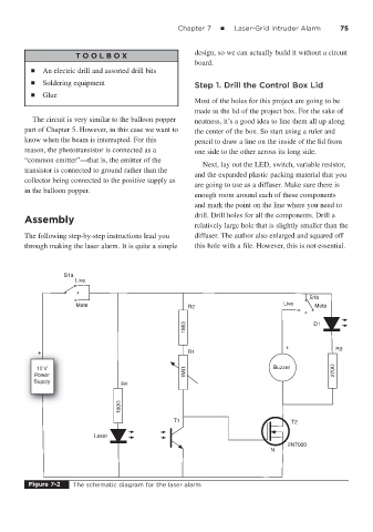
Figure 7-2 The schematic diagram for the laser alarm