
Page 97 - 15 Dangerously Mad Projects for the Evil Genius
P. 97
76 15 Dangerously Mad Projects for the Evil Genius
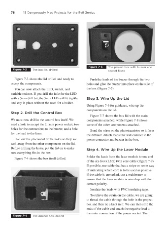
Figure 7-5 The project box with buzzer and
Figure 7-3 The box lid, drilled socket fitted
Figure 7-3 shows the lid drilled and ready to Push the leads of the buzzer through the two
accept the components. holes and glue the buzzer into place on the side of
You can now attach the LED, switch, and the box (Figure 7-5).
variable resistor. If you drill the hole for the LED
with a 5mm drill bit, the 5mm LED will fit tightly Step 3. Wire Up the Lid
and stay in place without the need for a holder.
Using Figure 7-6 for guidance, wire up the
components on the lid.
Step 2. Drill the Control Box
Figure 7-7 shows the box lid with the main
We must now drill in the control box itself. We components attached, while Figure 7-8 shows
need a hole to accept the 2.1mm power socket, two some of the other components attached.
holes for the connections to the buzzer, and a hole
Bend the wires on the phototransistor so it faces
for the lead to the laser.
the diffuser. Attach leads that will connect to the
Plan out the placement of the holes so they are power connector and buzzer in the box.
well away from the other components on the lid.
Before drilling the holes, put the lid on to make
Step 4. Wire Up the Laser Module
sure everything fits in the box.
Solder the leads from the laser module to one end
Figure 7-4 shows the box itself drilled.
of the six-foot (1.8m) twin core cable (Figure 7-9).
If possible, use cable that has a stripe or some way
of indicating which core is to be used as positive.
If the cable is unmarked, use a multimeter to
ensure that the laser module is wired up with the
correct polarity.
Insulate the leads with PVC insulating tape.
To relieve the strain on the cable, we are going
to thread the cable through the hole in the project
box and then tie a knot in it. We can then strip the
ends of the cable and attach the negative lead to
the outer connection of the power socket. The
Figure 7-4 The project box, drilled