
Page 99 - 15 Dangerously Mad Projects for the Evil Genius
P. 99
78 15 Dangerously Mad Projects for the Evil Genius
Figure 7-8 The box lid, partially assembled
less easy to reach as other things are soldered
into place.
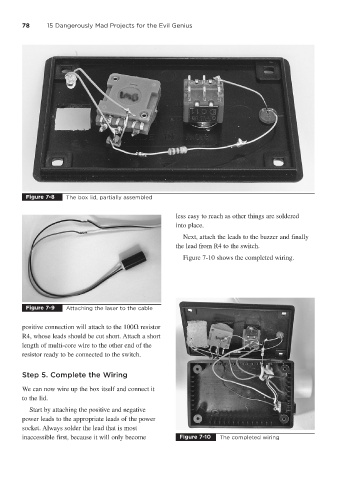
Next, attach the leads to the buzzer and finally
the lead from R4 to the switch.
Figure 7-10 shows the completed wiring.
Figure 7-9 Attaching the laser to the cable
positive connection will attach to the 100 resistor
R4, whose leads should be cut short. Attach a short
length of multi-core wire to the other end of the
resistor ready to be connected to the switch.
Step 5. Complete the Wiring
We can now wire up the box itself and connect it
to the lid.
Start by attaching the positive and negative
power leads to the appropriate leads of the power
socket. Always solder the lead that is most
inaccessible first, because it will only become Figure 7-10 The completed wiring