
Page 104 - 15 Dangerously Mad Projects for the Evil Genius
P. 104
Chapter 8 ■ Persistence-of-Vision Display 83
This is one of the most convenient things about ■ Sound
using an Arduino. Many microcontroller boards ■ Motor control
use separate programming hardware to get
■ GPS tracking
programs into the microcontroller. With Arduino,
it’s all contained on the board itself. Searching the Internet for “Arduino Shields”
should produce lots of interesting results if you
On both edges of the board are two rows of
want to go further into the world of Arduino. In
connectors. The row at the top of the diagram is
fact, one book in the Evil Genius series by this
mostly digital (on/off) pins, and any marked with
author concentrates solely on the Arduino. Its title:
“pwm” can be used as analog outputs.
30 Arduino Projects for the Evil Genius.
The bottom row of connectors has useful
power connections on the left, and analog inputs
on the right. Persistence-of-Vision Display
These connectors are arranged like this so that
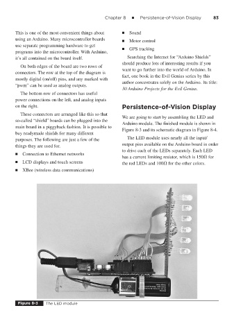
We are going to start by assembling the LED and
so-called “shield” boards can be plugged into the
Arduino module. The finished module is shown in
main board in a piggyback fashion. It is possible to
Figure 8-3 and its schematic diagram in Figure 8-4.
buy readymade shields for many different
The LED module uses nearly all the input/
purposes. The following are just a few of the
output pins available on the Arduino board in order
things they are used for.
to drive each of the LEDs separately. Each LED
■ Connection to Ethernet networks
has a current limiting resistor, which is 150 for
■ LCD displays and touch screens the red LEDs and 100 for the other colors.
■ XBee (wireless data communications)
Figure 8-3 The LED module