
Page 106 - 15 Dangerously Mad Projects for the Evil Genius
P. 106
Chapter 8 ■ Persistence-of-Vision Display 85
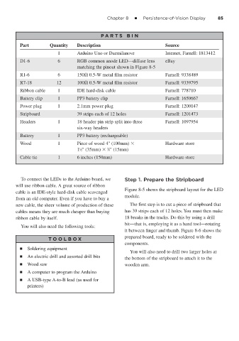
P A RT S BIN
Part Quantity Description Source
1 Arduino Uno or Duemilanove Internet, Farnell: 1813412
D1-6 6 RGB common anode LED—diffuse lens eBay
matching the pinout shown in Figure 8-5
R1-6 6 150 0.5-W metal film resistor Farnell: 9338489
R7-18 12 100 0.5-W metal film resistor Farnell: 9339795
Ribbon cable 1 IDE hard-disk cable Farnell: 778710
Battery clip 1 PP3 battery clip Farnell: 1650667
Power plug 1 2.1mm power plug Farnell: 1200147
Stripboard 39 strips each of 12 holes Farnell: 1201473
Headers 1 18-header pin strip split into three Farnell: 1097954
six-way headers
Battery 1 PP3 battery (rechargeable)
Wood 1 Piece of wood 4" (100mm) Hardware store
5
1
1 ⁄2" (35mm) ⁄8" (15mm)
Cable tie 1 6 inches (150mm) Hardware store
To connect the LEDs to the Arduino board, we Step 1. Prepare the Stripboard
will use ribbon cable. A great source of ribbon
Figure 8-5 shows the stripboard layout for the LED
cable is an IDE-style hard-disk cable scavenged
module.
from an old computer. Even if you have to buy a
new cable, the sheer volume of production of these The first step is to cut a piece of stripboard that
cables means they are much cheaper than buying has 39 strips each of 12 holes. You must then make
ribbon cable by itself. 18 breaks in the tracks. Do this by using a drill
bit—that is, employing it as a hand tool—rotating
You will also need the following tools:
it between finger and thumb. Figure 8-6 shows the
prepared board, ready to be soldered with the
T OOLBO X
components.
■ Soldering equipment
You will also need to drill two larger holes at
■ An electric drill and assorted drill bits
the bottom of the stripboard to attach it to the
■ Wood saw wooden arm.
■ A computer to program the Arduino
■ A USB-type A-to-B lead (as used for
printers)