
Page 109 - 15 Dangerously Mad Projects for the Evil Genius
P. 109
88 15 Dangerously Mad Projects for the Evil Genius
Step 3. Solder the LEDs Step 4. Solder the Ribbon Cable
Place the LEDs into position, ensuring they are the We are going to use three lengths of ribbon cable,
correct way around. Then, starting at one end of each with six wires. At the stripboard end, the
the board, solder each LED into place. To keep the cables will be soldered into place, and at the other
LEDs as straight as possible, solder one lead of the end, the ribbon cable will be soldered to header
LED, then reposition the LED from the front if pins so we can easily connect and disconnect the
required and solder the other leads into place. Arduino board.
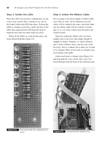
When all the LEDs are soldered into place, the Begin by cutting the ribbon cable into three
board should look like Figure 8-8. lengths each of six wires; the lengths should be
roughly 4 ⁄2 inches (120mm), 3 ⁄2 inches (90mm),
1
1
and 2 inches (50mm). Then, strip the ends of all
the wires. This is a tedious job as there are 36 ends
to be stripped. When all the ends are stripped, they
need tinning with solder.
Solder each lead to a header strip (Figure 8-9)
and then push the wires on the other end of the
board through from the front of the stripboard and
Figure 8-8 The board with all components in
Figure 8-9 Connecting the header strip
place