
Page 95 - 3D Fibre Reinforced Polymer Composites
P. 95
84 30 Fibre Reinforced Polymer Composites
Replacing the iso-strain assumption with an iso-stress assumption throughout the unit
cell, we can find the effective compliance matrix as follows:
1
IISw(y)]dV+ I[S'(x)]dV+ /[S"]dV (4.41)
Vf vm
In the iso-stress assumption, it is assumed that the stresses are uniform throughout the
unit cell when subject to a homogeneous boundary condition of constant surface
tractions as defined in equation (4.9). Similarly, a set of closed form expressions for the
effective compliance constants can be obtained.
The 3D fabric geometry model, initially developed by KO and Chou (1989) to study
the compressive behaviour of braided metal-matrix composites, was used by
Vandeurzen et a1 (1996a, 1996b and 1998) to develop 3D elastic models for woven
fabric composites. In the fabric geometry model, different yarn systems in a
macroscopic unit cell are defined according to the yam orientation, and each yarn
system is treated as a unidirectional lamina. By assuming that all yam systems have the
same strains, i.e., introducing an iso-strain condition in all yarns, the effective stiffness
matrix of the composite unit cell can be calculated as the weighted sum of the stiffness
matrices of all the yarn systems. Vandeurzen et a1 (1996a,b) carried out an extensive
geometric analysis of woven fabric composites, and then established a macro- and
micro-partition procedure to describe even the most complex 2D woven composite
structures, with a library of 108 rectangular macro-cells and a library of geometric
parameters. The procedure allows definition of the yarn systems in, generally speaking,
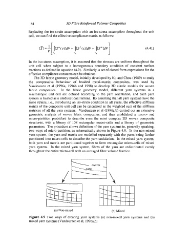
two ways of micro-partition, as schematically shown in Figure 4.9. In the non-mixed
yam system, the yarn and matrix are modelled separately with the yarns being further
partitioned into micro-cells to describe the yarn undulation. In the mixed yarn system,
both yam and matrix are partitioned together to form rectangular micro-cells of mixed
yarn system. In the mixed yarn system, fibres of the yarn are redistributed evenly
throughout the entire micro-cell with an averaged fibre volume fraction.
(a) Non-mixed (b) Mixed
Figure 4.9 Two ways of creating yarn systems (a) non-mixed yarn systems and (b)
mixed yam systems (Vandeurzen et al, 1996a,b)