
Page 21 - A Practical Introduction to Optical Mineralogy
P. 21
THE MICROSCOPIC STUDY OF MINERALS SYSTEMATIC DESCRIPTION OF MINERALS
1.3.2 Properties under crossed polars
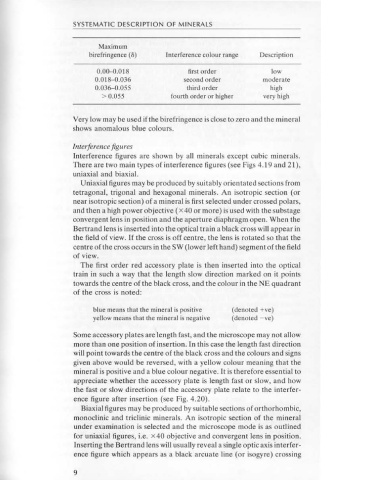
Maximum
The analyser is inserted into the optical path to give a dark, colourful birefringence ( ll) Interference colour range Description
image.
0.00-0.018 first order low
0.018-0.036 second order moderate
Isotropism 0.036-0.055 third order high
Minerals belonging to the cubic system are isotropic and remain dark > 0.055 fourth order or higher very high
under crossed polars whatever their optical orientation. All other min-
erals are anisotropic and usually appear coloured and go into extinction
Very low may be used ifthe birefringence is close to zero and the mineral
(that is, go dark) four times during a complete rotation of the mineral
shows anomalous blue colours.
section. This property, however, varies with crystallographic orienta-
tion, and each mineral possesses at least one orientation which will make
Interference figures
the crystal appear to be isotropic. For example, in tetragonal, trigonal
Interference figures are shown by all minerals except cubic minerals.
and hexagonal minerals, sections cut perpendicular to the c axis are
There are two main types of interference figures (see Figs 4.19 and 21 ),
always isotropic.
uniaxial and biaxial.
Uniaxial figures may be produced by suitably orientated sections from
Birefringence and interference colour tetragonal, trigonal and hexagonal minerals. An isotropic section (or
The colour of most anisotropic minerals under crossed polars varies, near isotropic section) of a mineral is first selected under crossed polars,
the same mineral showing different colours depending on its crystal- and then a high power objective ( x 40 or more) is used with the substage
lographic orientation. Thus quartz may vary from grey to white, and convergent lens in position and the aperture diaphragm open. When the
olivine may show a whole range of colours from grey to red or blue or Bertrand lens is inserted into the optical train a black cross will appear in
green. These are colours on Newton's Scale, which is divided into the field of view. If the cross is off centre, the lens is rotated so that the
several orders: centre of the cross occurs in the SW (lower left hand) segment of the field
of view.
The first order red accessory plate is then inserted into the optical
Order Colours
train in such a way that the length slow direction marked on it points
first grey, white, yellow, red towards the centre of the black cross, and the colour in the NE quadrant
second violet, blue, green, yellow, orange, red of the cross is noted:
third indigo, green, blue, yellow, red, violet
fourth and above pale pinks and green blue means that the mineral is positive (denoted +ve)
yellow means that the mineral is negative (denoted - ve)
A Newton's Scale of colours can be found on the back cover of this book. Some accessory plates are length fast, and the microscope may not allow
These orders represent interference colours; they depend on the thick- more than one position of insertion. In this case the length fast direction
ness of the thin section mineral and the birefringence, which is the will point towards the centre of the black cross and the colours and signs
difference between the two refractive indices of the anisotropic mineral given above would be reversed, with a yellow colour meaning that the
grain. The thin section thickness is constant (normally 30 microns) and mineral is positive and a blue colour negative. It is therefore essential to
so interference colours depend on birefringence; the greater the bi- appreciate whether the accessory plate is length fast or slow, and how
refringence, the higher the order of the interference colours. Since the the fast or slow directions of the accessory plate relate to the interfer-
maximum and minimum refractive indices of any mineral are oriented ence figure after insertion (see Fig. 4.20).
along precise crystallographic directions, the highest interference col- Biaxial figures may be produced by suitable sections of orthorhombic,
ours will be shown by a mineral section which has both maximum and monoclinic and triclinic minerals. An isotropic section of the mineral
minimum Rls in the plane of the section. This section will have the under examination is selected and the microscope mode is as outlined
maximum birefringence (denoted 8) of the mineral. Any differently for uniaxial figures, i.e. X40 objective and convergent lens in position.
oriented section will have a smaller birefringence and show lower col- Inserting the Bertrand lens will usually reveal a single optic axis interfer-
ours. The descriptive terms used in Chapter 2 are as follows: ence figure which appears as a black arcuate line (or isogyre) crossing
8 9