
Page 29 - A Practical Introduction to Optical Mineralogy
P. 29
THE MICROSCOPIC STUDY OF MINERALS THE APPEARANCE OF POLISHED SECTIONS
Analyser Figure 1.6 Correctly centred aperture diaphragm
for a plate glass reflector
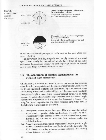
Centring of the crosswires :€8> .
The analyser may be moved in and out of the optical train and rotated image with Bertrand lens inserted
aperture > and aperture diaphragm closed
through small angles during observation of the specimen. The reason for
diaphragm.
rotation of the analyser is to enhance the effects of anisotropy. It is taken
out to give plane polarised light (PPL), the field appearing bright, and aperture · · ·
diaphragm · ·
put in to give crossed polars (XPOLS), the field appearing dark. Like the
polariser, it is usually made of polarising film. On some microscopes the
analyser is fixed in orientation and the polariser is designed to rotate.
The effect is the same in both cases, but it is easier to explain the
behaviour of light assuming a rotating analyser (Section 5.3). Correctly centred aperture diaphragm
for a prism reflector
image with Bertrand lens inserted and
The Bertrand lens aperture diaphragm closed
edge of
This is usually little used in reflected-light microscopy, especially prism
by beginners. The polarisation figures obtained are similar, but differ
in origin and use, to the interference figures of transmitted-light
microscopy. shows the aperture diaphragm correctly centred for glass plate and
Isotropic minerals give a black cross which is unaffected by rotation of prism reflectors.
the stage but splits into two isogyres on rotation of the analyser. Lower The illuminato; field diaphragm is used simply to control scattered
symmetry minerals give a black cross in the extinction position, but light. It can usually be focused and should be in focus at the same
the cross separates into isogyres on rotation of either the stage position as the specimen image. The field diaphragm should be opened
or the analyser. Colour fringes on the isogyres relate to dispersion of the until it just disappears from the field of view.
rotation properties.
1.5 The appearance of polished sections under the
Light control
Reflected-light microscopes are usually designed to give Kohler-type reflected-light microscope
critical illumination (Galopin & Henry 1972, p. 58). As far as the user is
On first seeing a polished section of a rock or ore sample the observer
concerned, this means that the aperture diaphragm and the lamp
filament can be seen using conoscopic light (Bertrand lens in) and the often finds that interpretation of the image is rather difficult. One reason
for this is that most students use transmitted light for several years
field diaphragm can be seen using orthoscopic light (Bertrand lens out).
A lamp rheostat is usually available on a reflected-light microscope to before being introduced to reflected light, and they are conditioned into
interpreting bright areas as being transparent and dark areas as being
enable the light intensity to be varied. A very intense light source is
necessary for satisfactory observation using crossed polars. However, opaque; for polished sections the opposite is the case! It is best to begin
·examination of a polished section such as that illustrated in Figure 1.7 by
for PPL observations the rheostat is best left at the manufacturer's
recommended value, which should result in a colour temperature of the using low power magnification and plane polarised light, when most of
A source. The problem with using a decreased lamp intensity to the following features can be observed:
decrease image brightness is that this changes the overall colour of the
image. Ideally, neutral density filters should be used to decrease bright- (a) Transparent phases appear dark grey. This is because they reflect
ness if the observer finds it uncomfortable. In this respect, binocular only a small proportion of the incident light, typically 3 to 15 %.
microscopes prove less wearisome on the eyes than monocular Occasionally bright patches are seen within areas of transparent
microscopes. minerals, and are due to reflection from surfaces under the
Opening of the aperture diaphragm decreases resolution, decreases polished surface.
the depth of focus and increases brightness. It should ideally be kept (b) Absorbing phases (opaques or ore minerals) appear grey to bright
only partially open for PPL observation but opened fully when using white as they reflect much more of the incident light, typically 15 to
crossed polars. If the aperture diaphragm can be adjusted, it is viewed 95 %. Some absorbing minerals appear coloured, but usually
using the Bertrand lens or by removing the ocular (eyepiece). Figure 1.6 colour tints are very slight.
16 17