
Page 137 - ARM Based Microcontroller Projects Using MBED
P. 137
7.16 PROJECT 13—7-SEGMENT LED DISPLAY 123
7.16.4 Circuit Diagram
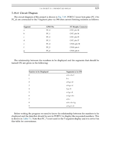
The circuit diagram of the project is shown in Fig. 7.69. PORT C lower byte pins (PC_0 to
PC_6) are connected to the 7-segment pins via 390 ohm current limiting resistors as follows:
Segment GPIO Pin ST Morpho Connector
a PC_0 CN7, pin 38
b PC_1 CN7, pin 36
c PC_2 CN7, pin 35
d PC_3 CN7, pin 37
e PC_4 CN10, pin 34
f PC_5 CN10, pin 6
g PC_6 CN10, pin 4
The relationship between the numbers to be displayed and the segments that should be
turned ON are given in the following:
Number to be Displayed Segments to be ON
0 a b c d e f
1 b c
2 a b g e d
3 a b g c d
4 f g c b
5 a f g c d
6 a f g e d c
7 a b c
8 a b c d e f g
9 a b g f c d
Before writing the program we need to know the relationship between the numbers to be
displayed and the data that should be sent to PORT C to display the requested numbers. This
is shown in Table 7.1. Note that PC_7 is not used in the 7-segment display and it is set to 0 in
this table for convenience.