
Page 132 - ARM Based Microcontroller Projects Using MBED
P. 132
118 7. USING THE Mbed WITH SIMPLE PROJECTS
7.15.3 Block Diagram
The block diagram of the project is shown in Fig. 7.60.
7.15.4 Circuit Diagram
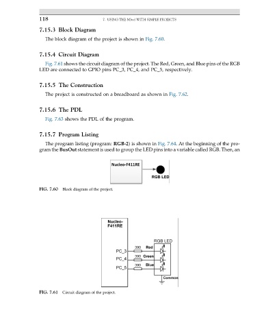
Fig. 7.61 shows the circuit diagram of the project. The Red, Green, and Blue pins of the RGB
LED are connected to GPIO pins PC_3, PC_4, and PC_5, respectively.
7.15.5 The Construction
The project is constructed on a breadboard as shown in Fig. 7.62.
7.15.6 The PDL
Fig. 7.63 shows the PDL of the program.
7.15.7 Program Listing
The program listing (program: RGB-2) is shown in Fig. 7.64. At the beginning of the pro-
gram the BusOut statement is used to group the LED pins into a variable called RGB. Then, an
FIG. 7.60 Block diagram of the project.
FIG. 7.61 Circuit diagram of the project.