
Page 129 - ARM Based Microcontroller Projects Using MBED
P. 129
7.14 PROJECT 11—RGB LED CONTROL 115
7.14.5 The Construction
Fig. 7.57 shows the project build on a breadboard. The RGB LED is connected to the
Nucleo-F411RE board using jumper wires.
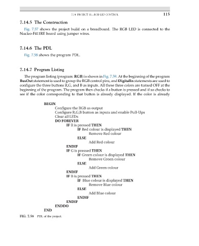
7.14.6 The PDL
Fig. 7.58 shows the program PDL.
7.14.7 Program Listing
The program listing (program: RGB) is shown in Fig. 7.59. At the beginning of the program
BusOut statement is used to group the RGB control pins, and DigitalIn statements are used to
configure the three buttons R,G, and B as inputs. All these three colors are turned OFF at the
beginning of the program. The program then checks if a button is pressed and if so checks to
see if the color corresponding to that button is already displayed. If the color is already
BEGIN
Configure the RGB as output
Configure R,G,B button as inputs and enable Pull-Ups
Clear all LEDs
DO FOREVER
IF R is pressed THEN
IF Red colour is displayed THEN
Remove Red colour
ELSE
Add Red colour
ENDIF
IF G is pressed THEN
IF Green colour is displayed THEN
Remove Green colour
ELSE
Add Green colour
ENDIF
IF B is pressed THEN
IF Blue colour is displayed THEN
Remove Blue colour
ELSE
Add Blue colour
ENDIF
ENDIF
ENDDO
END
FIG. 7.58 PDL of the project.