
Page 128 - ARM Based Microcontroller Projects Using MBED
P. 128
114 7. USING THE Mbed WITH SIMPLE PROJECTS
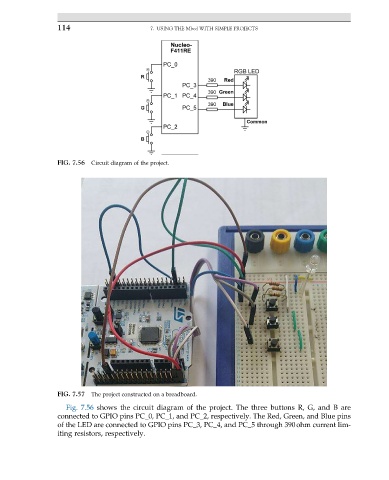
FIG. 7.56 Circuit diagram of the project.
FIG. 7.57 The project constructed on a breadboard.
Fig. 7.56 shows the circuit diagram of the project. The three buttons R, G, and B are
connected to GPIO pins PC_0, PC_1, and PC_2, respectively. The Red, Green, and Blue pins
of the LED are connected to GPIO pins PC_3, PC_4, and PC_5 through 390ohm current lim-
iting resistors, respectively.