
Page 127 - ARM Based Microcontroller Projects Using MBED
P. 127
7.14 PROJECT 11—RGB LED CONTROL 113
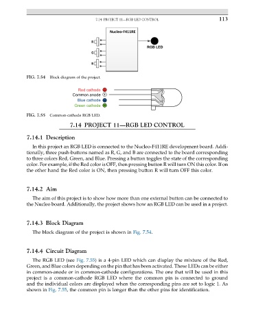
FIG. 7.54 Block diagram of the project.
Red cathode –
Common anode +
Blue cathode –
Green cathode –
FIG. 7.55 Common-cathode RGB LED.
7.14 PROJECT 11—RGB LED CONTROL
7.14.1 Description
In this project an RGB LED is connected to the Nucleo-F411RE development board. Addi-
tionally, three push-buttons named as R, G, and B are connected to the board corresponding
to three colors Red, Green, and Blue. Pressing a button toggles the state of the corresponding
color. For example, if the Red color is OFF, then pressing button R will turn ON this color. If on
the other hand the Red color is ON, then pressing button R will turn OFF this color.
7.14.2 Aim
The aim of this project is to show how more than one external button can be connected to
the Nucleo board. Additionally, the project shows how an RGB LED can be used in a project.
7.14.3 Block Diagram
The block diagram of the project is shown in Fig. 7.54.
7.14.4 Circuit Diagram
The RGB LED (see Fig. 7.55) is a 4-pin LED which can display the mixture of the Red,
Green, and Blue colors depending on the pin that has been activated. These LEDs can be either
in common-anode or in common-cathode configurations. The one that will be used in this
project is a common-cathode RGB LED where the common pin is connected to ground
and the individual colors are displayed when the corresponding pins are set to logic 1. As
shown in Fig. 7.55, the common pin is longer than the other pins for identification.