
Page 124 - ARM Based Microcontroller Projects Using MBED
P. 124
110 7. USING THE Mbed WITH SIMPLE PROJECTS
FIG. 7.49 Button state is normally at logic 0.
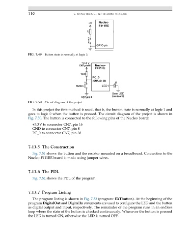
FIG. 7.50 Circuit diagram of the project.
In this project the first method is used, that is, the button state is normally at logic 1 and
goes to logic 0 when the button is pressed. The circuit diagram of the project is shown in
Fig. 7.50. The button is connected to the following pins of the Nucleo board:
+3.3V to connector CN7, pin 16
GND to connector CN7, pin 8
PC_0 to connector CN7, pin 38
7.13.5 The Construction
Fig. 7.51 shows the button and the resistor mounted on a breadboard. Connection to the
Nucleo-F411RE board is made using jumper wires.
7.13.6 The PDL
Fig. 7.52 shows the PDL of the program.
7.13.7 Program Listing
The program listing is shown in Fig. 7.53 (program: EXTbutton). At the beginning of the
program DigitalOut and DigitalIn statements are used to configure the LED and the button
as digital output and input, respectively. The remainder of the program runs in an endless
loop where the state of the button is checked continuously. Whenever the button is pressed
the LED is turned ON, otherwise the LED is turned OFF.