
Page 120 - ARM Based Microcontroller Projects Using MBED
P. 120
106 7. USING THE Mbed WITH SIMPLE PROJECTS
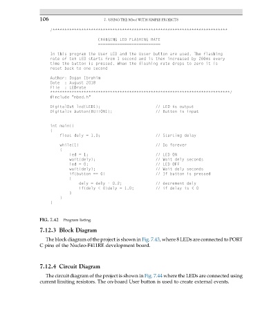
/*************************************************************************
CHANGING LED FLASHING RATE
==========================
In this program the User LED and the Usser button are used. The flashing
rate of teh LED starts from 1 second and is then increased by 200ms every
time the button is pressed. When the flashing rate drops to zero it is
reset back to one second
Author: Dogan Ibrahim
Date : August 2018
File : LEDrate
***************************************************************************/
#include "mbed.h"
DigitalOut led(LED1); // LED is output
DigitalIn button(BUTTON1); // Button is input
int main()
{
float dely = 1.0; // Starting delay
while(1) // Do forever
{
led = 1; // LED ON
wait(dely); // Wait dely seconds
led = 0; // LED OFF
wait(dely); // Wait dely seconds
if(button == 0) // If button is pressed
{
dely = dely - 0.2; // decrement dely
if(dely < 0)dely = 1.0; // if delay is < 0
}
}
}
FIG. 7.42 Program listing.
7.12.3 Block Diagram
The block diagram of the project is shown in Fig. 7.43, where 8 LEDs are connected to PORT
C pins of the Nucleo-F411RE development board.
7.12.4 Circuit Diagram
The circuit diagram of the project is shown in Fig. 7.44 where the LEDs are connected using
current limiting resistors. The on-board User button is used to create external events.