
Page 119 - ARM Based Microcontroller Projects Using MBED
P. 119
7.12 PROJECT 9—BINARY EVENT COUNTING WITH LEDs 105
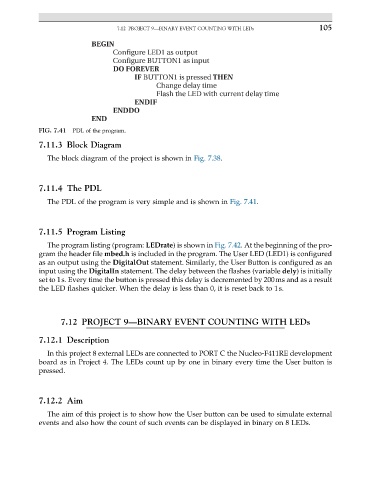
BEGIN
Configure LED1 as output
Configure BUTTON1 as input
DO FOREVER
IF BUTTON1 is pressed THEN
Change delay time
Flash the LED with current delay time
ENDIF
ENDDO
END
FIG. 7.41 PDL of the program.
7.11.3 Block Diagram
The block diagram of the project is shown in Fig. 7.38.
7.11.4 The PDL
The PDL of the program is very simple and is shown in Fig. 7.41.
7.11.5 Program Listing
The program listing (program: LEDrate) is shown in Fig. 7.42. At the beginning of the pro-
gram the header file mbed.h is included in the program. The User LED (LED1) is configured
as an output using the DigitalOut statement. Similarly, the User Button is configured as an
input using the DigitalIn statement. The delay between the flashes (variable dely) is initially
set to 1s. Every time the button is pressed this delay is decremented by 200ms and as a result
the LED flashes quicker. When the delay is less than 0, it is reset back to 1s.
7.12 PROJECT 9—BINARY EVENT COUNTING WITH LEDs
7.12.1 Description
In this project 8 external LEDs are connected to PORT C the Nucleo-F411RE development
board as in Project 4. The LEDs count up by one in binary every time the User button is
pressed.
7.12.2 Aim
The aim of this project is to show how the User button can be used to simulate external
events and also how the count of such events can be displayed in binary on 8 LEDs.