
Page 117 - ARM Based Microcontroller Projects Using MBED
P. 117
7.10 PROJECT 7—LED CONTROL WITH PUSH-BUTTON 103
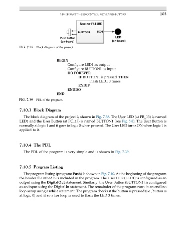
FIG. 7.38 Block diagram of the project.
BEGIN
Configure LED1 as output
Configure BUTTON1 as input
DO FOREVER
IF BUTTON1 is pressed THEN
Flash LED1 3 times
ENDIF
ENDDO
END
FIG. 7.39 PDL of the program.
7.10.3 Block Diagram
The block diagram of the project is shown in Fig. 7.38. The User LED (at PB_13) is named
LED1 and the User Button (at PC_13) is named BUTTON1 (see Fig. 5.8). The User Button is
normally at logic 1 and it goes to logic 0 when pressed. The User LED turns ON when logic 1 is
applied to it.
7.10.4 The PDL
The PDL of the program is very simple and is shown in Fig. 7.39.
7.10.5 Program Listing
The program listing (program: Push) is shown in Fig. 7.40. At the beginning of the program
the header file mbed.h is included in the program. The User LED (LED1) is configured as an
output using the DigitalOut statement. Similarly, the User Button (BUTTON1) is configured
as an input using the DigitalIn statement. The remainder of the program runs in an endless
loop setup using a while statement. The program checks if the button is pressed (i.e., button is
at logic 0) and if so a for loop is used to flash the LED 3 times.