
Page 123 - ARM Based Microcontroller Projects Using MBED
P. 123
7.13 PROJECT 10—USING AN EXTERNAL BUTTON 109
7.13 PROJECT 10—USING AN EXTERNAL BUTTON
7.13.1 Description
In this project an external button is connected to port pin PC_0 (connector CN7, pin 38) of
the 8 Nucleo-F411RE development board. The User LED (LED1) is turned ON whenever the
button is pressed.
7.13.2 Aim
The aim of this project is to show how an external button can be connected to the Nucleo-
F411RE development board.
7.13.3 Block Diagram
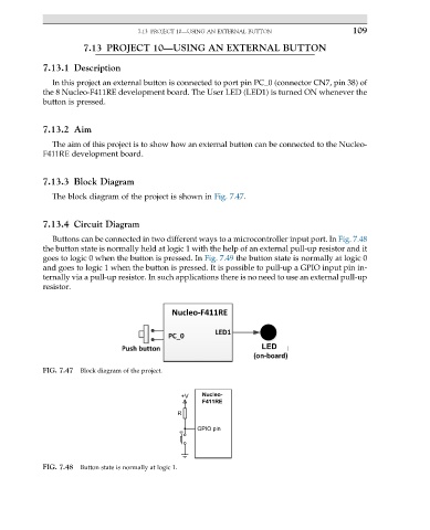
The block diagram of the project is shown in Fig. 7.47.
7.13.4 Circuit Diagram
Buttons can be connected in two different ways to a microcontroller input port. In Fig. 7.48
the button state is normally held at logic 1 with the help of an external pull-up resistor and it
goes to logic 0 when the button is pressed. In Fig. 7.49 the button state is normally at logic 0
and goes to logic 1 when the button is pressed. It is possible to pull-up a GPIO input pin in-
ternally via a pull-up resistor. In such applications there is no need to use an external pull-up
resistor.
FIG. 7.47 Block diagram of the project.
FIG. 7.48 Button state is normally at logic 1.