
Page 243 - ARM Based Microcontroller Projects Using MBED
P. 243
8.31 PROJECT 26—SINE WAVEFORM 229
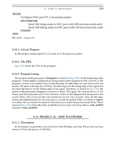
BEGIN
Configure DAC port PA_4 as analog output
DO FOREVER
Send 100 rising steps to DAC port with 100 microseconds each
Send 100 falling steps to DAC port with 100 microseconds each
ENDDO
END
FIG. 8.101 Program PDL.
8.30.3 Circuit Diagram
In this project, analog input PA_4 is used as in the previous project.
8.30.4 The PDL
Fig. 8.101 shows the PDL of the program.
8.30.5 Program Listing
The program listing (program: Triangular) is shown in Fig. 8.102. At the beginning of the
program, variable aout is configured as analog output and is assigned to DAC port PA_4. The
program consists of an endless loop. Inside this loop, two for loops are used where each one
iterates 100 times with step size of 100 μs. One for loop is for the rising edge of the signal and
the other for loop is for the falling edge of the signal. Therefore, as shown in Fig. 8.103, the
period of the generated triangular waveform is 20ms. This figure the vertical axis is 1V/di-
vision, and the horizontal axis is 5ms/division. Notice in this diagram that the period is not
exactly 20ms. This is because the wait statements are not very accurate. Also, the for state-
ments add additional time to the loop and as a result the period of the waveform is slightly
over 20ms. We can reduce the delay by trial and error to make the period exactly 20ms. This is
shown in Fig. 8.104 where the delay inside the two for loops were 92 μs, that is, wait_us(92.0)
instead of wait_us(100.0).
8.31 PROJECT 26—SINE WAVEFORM
8.31.1 Description
In this project, we generate a sine waveform with 100 steps, each step 100 μs, thus having a
period of 10ms (frequency of 100kHz).