Page 244 - ARM Based Microcontroller Projects Using MBED
P. 244

230                          8. INTERMEDIATE LEVEL PROJECTS
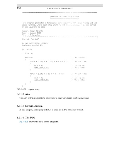
                      /*************************************************************************

                                                  GENERATE TRIANGULAR WAVEFORM
                                                  ============================
                      This program generates a triangular waveform with 100 steps rising and 100
                      steps falling, where each step width is 100 microseconds. i.e. the period
                      of the waveform is 20ms
                      Author: Dogan Ibrahim
                      Date  : August 2018
                      File  : Triangular
                      **************************************************************************/
                      #include "mbed.h"
                      Serial MyPC(USBTX, USBRX);
                      AnalogOut aout(PA_4);

                      int main()
                      {
                         float k;

                         while(1)                                      // Do forever
                         {
                              for(k = 0.0f; k < 1.0f; k = k + 0.01f)   // Do 100 times
                              {
                                  aout = k;                            // Analog out
                                  wait_us(100.0);                      // Wait 100us
                              }

                              for(k = 1.0f; k > 0; k = k - 0.01f)      // Do 100 times
                              {
                                  aout = k;                            // Analog out
                                  wait_us(100.0);                      // Wait 100us
                              }
                         }
                      }
                 FIG. 8.102  Program listing.

                 8.31.2 Aim
                   The aim of this project is to show how a sine waveform can be generated.


                 8.31.3 Circuit Diagram
                   In this project, analog input PA_4 is used as in the previous project.


                 8.31.4 The PDL
                   Fig. 8.105 shows the PDL of the program.
   239   240   241   242   243   244   245   246   247   248   249