
Page 267 - ARM Based Microcontroller Projects Using MBED
P. 267
8.36 PROJECT 30—ELECTRONIC ORGAN 253
8.36.4 Circuit Diagram
The circuit diagram of the project is same as in Fig. 8.118 where the buzzer is connected to
PWM port PA_8 (PWM1/1, pin 23 connector CN10) of the Nucleo-F411RE development
board through a transistor switch.
8.36.5 The PDL
The frequencies of the musical notes starting from C5 are given below (sharps and flats are
not shown here). The harmonic of a note is obtained by doubling the frequency. For example,
the frequency of C6 is 2 523.25¼1046.50Hz.
Notes C5 D5 E5 F5 G5 A5 B5 C6
Hz 523.25 587.33 659.25 698.46 783.99 880.00 987.77 1046.50
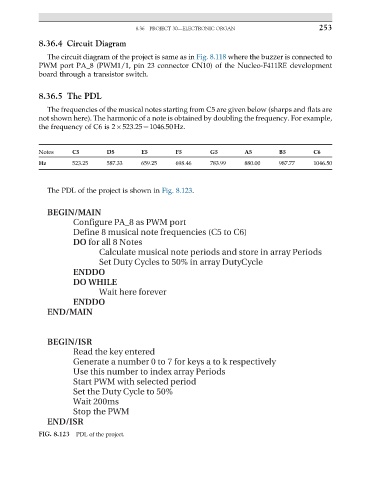
The PDL of the project is shown in Fig. 8.123.
BEGIN/MAIN
Configure PA_8 as PWM port
Define 8 musical note frequencies (C5 to C6)
DO for all 8 Notes
Calculate musical note periods and store in array Periods
Set Duty Cycles to 50% in array DutyCycle
ENDDO
DO WHILE
Wait here forever
ENDDO
END/MAIN
BEGIN/ISR
Read the key entered
Generate a number 0 to 7 for keys a to k respectively
Use this number to index array Periods
Start PWM with selected period
Set the Duty Cycle to 50%
Wait 200ms
Stop the PWM
END/ISR
FIG. 8.123 PDL of the project.