
Page 271 - ARM Based Microcontroller Projects Using MBED
P. 271
8.38 SUMMARY 257
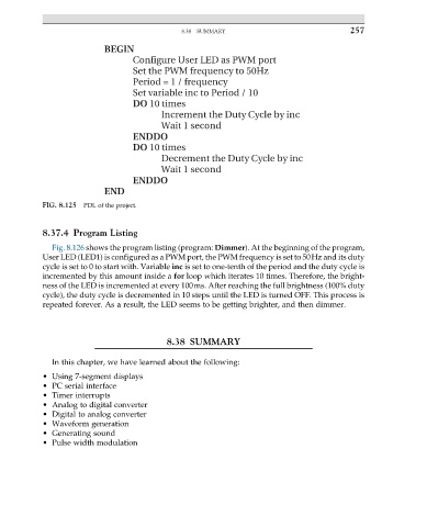
BEGIN
Configure User LED as PWM port
Set the PWM frequency to 50Hz
Period = 1 / frequency
Set variable inc to Period / 10
DO 10 times
Increment the Duty Cycle by inc
Wait 1 second
ENDDO
DO 10 times
Decrement the Duty Cycle by inc
Wait 1 second
ENDDO
END
FIG. 8.125 PDL of the project.
8.37.4 Program Listing
Fig. 8.126 shows the program listing (program: Dimmer). At the beginning of the program,
User LED (LED1) is configured as a PWM port, the PWM frequency is set to 50Hz and its duty
cycle is set to 0 to start with. Variable inc is set to one-tenth of the period and the duty cycle is
incremented by this amount inside a for loop which iterates 10 times. Therefore, the bright-
ness of the LED is incremented at every 100ms. After reaching the full brightness (100% duty
cycle), the duty cycle is decremented in 10 steps until the LED is turned OFF. This process is
repeated forever. As a result, the LED seems to be getting brighter, and then dimmer.
8.38 SUMMARY
In this chapter, we have learned about the following:
• Using 7-segment displays
• PC serial interface
• Timer interrupts
• Analog to digital converter
• Digital to analog converter
• Waveform generation
• Generating sound
• Pulse width modulation