
Page 276 - ARM Based Microcontroller Projects Using MBED
P. 276
262 9. MOTOR CONTROL PROJECTS
FIG. 9.1 Block diagram of the project.
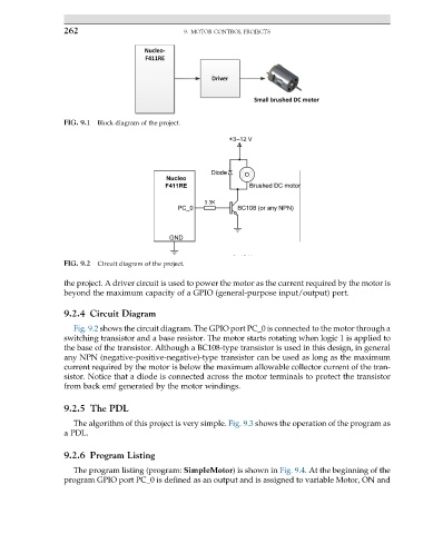
FIG. 9.2 Circuit diagram of the project.
the project. A driver circuit is used to power the motor as the current required by the motor is
beyond the maximum capacity of a GPIO (general-purpose input/output) port.
9.2.4 Circuit Diagram
Fig. 9.2 shows the circuit diagram. The GPIO port PC_0 is connected to the motor through a
switching transistor and a base resistor. The motor starts rotating when logic 1 is applied to
the base of the transistor. Although a BC108-type transistor is used in this design, in general
any NPN (negative-positive-negative)-type transistor can be used as long as the maximum
current required by the motor is below the maximum allowable collector current of the tran-
sistor. Notice that a diode is connected across the motor terminals to protect the transistor
from back emf generated by the motor windings.
9.2.5 The PDL
The algorithm of this project is very simple. Fig. 9.3 shows the operation of the program as
a PDL.
9.2.6 Program Listing
The program listing (program: SimpleMotor) is shown in Fig. 9.4. At the beginning of the
program GPIO port PC_0 is defined as an output and is assigned to variable Motor, ON and