
Page 279 - ARM Based Microcontroller Projects Using MBED
P. 279
9.3 PROJECT 2—CHANGING THE MOTOR ROTATION DIRECTION 265
9.3.2 Aim
The aim of this project is to show how the rotation direction of the motor can easily be
changed.
9.3.3 Block Diagram
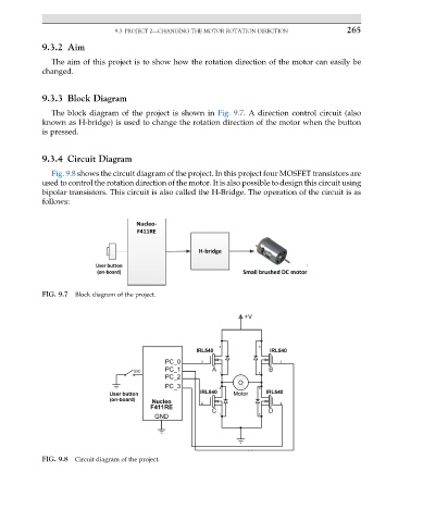
The block diagram of the project is shown in Fig. 9.7. A direction control circuit (also
known as H-bridge) is used to change the rotation direction of the motor when the button
is pressed.
9.3.4 Circuit Diagram
Fig. 9.8 shows the circuit diagram of the project. In this project four MOSFET transistors are
used to control the rotation direction of the motor. It is also possible to design this circuit using
bipolar transistors. This circuit is also called the H-Bridge. The operation of the circuit is as
follows:
FIG. 9.7 Block diagram of the project.
FIG. 9.8 Circuit diagram of the project.