
Page 283 - ARM Based Microcontroller Projects Using MBED
P. 283
9.4 PROJECT 3—SIMPLE SERVO MOTOR CONTROL 269
9.4.3 Block Diagram
Servo motors are DC motors with built-in feedback circuits so that the positions of their
shaft can be controlled accurately. These motors have three terminals: power, ground, and
control. The control terminal is driven with PWM waveform usually with a period of
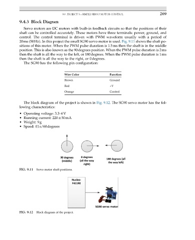
20ms (50Hz). In this project the small SG90 servo motor is used. Fig. 9.11 shows the shaft po-
sitions of this motor. When the PWM pulse duration is 1.5ms then the shaft is in the middle
position. This is also known as the 90degrees position. When the PWM pulse duration is 2ms
then the shaft is all the way to the left, or 180degrees. When the PWM pulse duration is 1ms
then the shaft is all the way to the right, or 0degrees.
The SG90 has the following pin configuration:
Wire Color Function
Brown Ground
Red +V
Orange Control
The block diagram of the project is shown in Fig. 9.12. The SG90 servo motor has the fol-
lowing characteristics:
• Operating voltage: 3.3–6V
• Running current: 220 50mA
• Weight: 9g
• Speed: 01s/60degrees
FIG. 9.11 Servo motor shaft positions.
FIG. 9.12 Block diagram of the project.