
Page 288 - ARM Based Microcontroller Projects Using MBED
P. 288
274 9. MOTOR CONTROL PROJECTS
FIG. 9.19 ULN2003 stepper driver module.
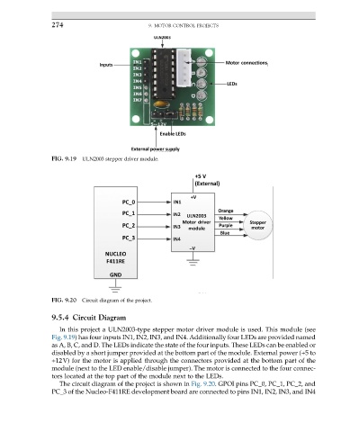
FIG. 9.20 Circuit diagram of the project.
9.5.4 Circuit Diagram
In this project a ULN2003-type stepper motor driver module is used. This module (see
Fig. 9.19) has four inputs IN1, IN2, IN3, and IN4. Additionally four LEDs are provided named
as A, B, C, and D. The LEDs indicate the state of the four inputs. These LEDs can be enabled or
disabled by a short jumper provided at the bottom part of the module. External power (+5 to
+12V) for the motor is applied through the connectors provided at the bottom part of the
module (next to the LED enable/disable jumper). The motor is connected to the four connec-
tors located at the top part of the module next to the LEDs.
The circuit diagram of the project is shown in Fig. 9.20. GPOI pins PC_0, PC_1, PC_2, and
PC_3 of the Nucleo-F411RE development board are connected to pins IN1, IN2, IN3, and IN4