
Page 284 - ARM Based Microcontroller Projects Using MBED
P. 284
270 9. MOTOR CONTROL PROJECTS
9.4.4 Circuit Diagram
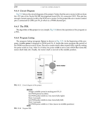
Fig. 9.13 shows the circuit diagram of the project. Notice that the servo motor is driven from
the +5V pin of the Nucle-F411RE development board (Pin 18, connector CN7). This pin has
enough current capacity to drive the SG90 servo motor. In this project the servo motor control
pin is connected to GPIO pin PA_8 which is a PWM channel pin.
9.4.5 The PDL
The algorithm of this project is very simple. Fig. 9.14 shows the operation of the program as
a PDL.
9.4.6 Program Listing
The program listing (program: Servo) is shown in Fig. 9.15. At the beginning of the pro-
gram variable pwm is assigned to PWM port PA_8. Inside the main program the period of
the PWM waveform is set to 20ms. The servo motor shaft is then turned fully right by setting
the pulse width to 1ms. After 3s of delay the pulse width is set to 2ms which then turns the
motor shaft fully left. Finally, the motor shaft is moved to the middle position.
FIG. 9.13 Circuit diagram of the project.
FIG. 9.14 Program PDL.