
Page 287 - ARM Based Microcontroller Projects Using MBED
P. 287
9.5 PROJECT 4—SIMPLE STEPPER MOTOR CONTROL 273
FIG. 9.17 Bipolar stepper motor windings.
TABLE 9.2 Bipolar Motor Excitation
Step a c b d
1 +
2 +
3 +
4 +
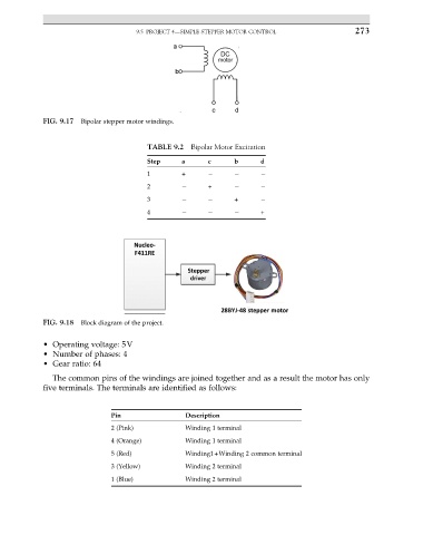
FIG. 9.18 Block diagram of the project.
• Operating voltage: 5V
• Number of phases: 4
• Gear ratio: 64
The common pins of the windings are joined together and as a result the motor has only
five terminals. The terminals are identified as follows:
Pin Description
2 (Pink) Winding 1 terminal
4 (Orange) Winding 1 terminal
5 (Red) Winding1+Winding 2 common terminal
3 (Yellow) Winding 2 terminal
1 (Blue) Winding 2 terminal