
Page 290 - ARM Based Microcontroller Projects Using MBED
P. 290
276 9. MOTOR CONTROL PROJECTS
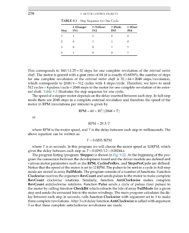
TABLE 9.3 Step Sequence for One Cycle
4 (Orange) 3 (Yellow) 2 (Pink) 1 (Blue)
Step IN1 IN2 IN3 IN4
1 1 1 0 0
2 0 1 1 0
3 0 0 1 1
4 1 0 0 1
This corresponds to 360/11.25¼32 steps for one complete revolution of the internal motor
shaft. The motor is geared with a gear ratio of 64 (it is exactly 63.68395), the number of steps
for one complete revolution of the external motor shaft is 32 64¼2048 steps/revolution,
which corresponds to 2048/4¼512 cycles with 4 steps/cycle. Therefore, we have to send
512 cycles 4 pulses/cycle¼2048 steps to the motor for one complete revolution of its exter-
nal shaft. Table 9.3 illustrates the step sequence for one cycle.
The speed of a stepper motor depends on the delay inserted between each step. In full-step
mode there are 2048 steps in a complete external revolution and therefore the speed of the
motor in RPM (revolutions per minute) is given by
3
RPM ¼ 60 10 = 2048 Tð Þ
or
RPM ¼ 29:3=T
where RPM is the motor speed, and T is the delay between each step in milliseconds. The
above equation can be written as
T ¼ 0:0293=RPM
where T is in seconds. In this program we will choose the motor speed as 12RPM, which
gives the delay between each step as T¼0.0293/12¼0.00244s.
The program listing (program: Stepper) is shown in Fig. 9.22. At the beginning of the pro-
gram the connection between the development board and the driver module are defined and
various motor parameters such as the RPM, CyclesPerRev, and StepsPerCycle are defined.
Notice that the speed of the motor is set to 12RPM. The pulses to be sent in a cycle in full-step
mode are stored in array FullMode. The program consists of a number of functions. Function
Clockwise receives the argument RevCount and sends pulses to the motor to make complete
RevCount clockwise rotations. Similarly, function AntiClockwise makes complete
RevCount anticlockwise rotations. Function Pulse sends a cycle of pulses (four pulses) to
the motor by calling function CheckBit which extracts the bits of array FullMode for a given
step and sends the extracted bits to the motor windings. The main program calculates the de-
lay between each step in seconds, calls function Clockwise with argument set to 3 to make
three complete revolutions. After 3s of delay function AntiClockwise is called with argument
3 so that three complete anticlockwise revolutions are made.