
Page 286 - ARM Based Microcontroller Projects Using MBED
P. 286
272 9. MOTOR CONTROL PROJECTS
9.5.2 Aim
The aim of this project is to show how a stepper motor can be controlled.
9.5.3 Block Diagram
Stepper motors rotate by small steps in response to applied voltage pulses. The motors
have several windings and the voltage steps must be applied in the correct sequences to turn
the motor shaft. Basically, there are two types of stepper motors: unipolar and bipolar.
Unipolar Stepper Motors
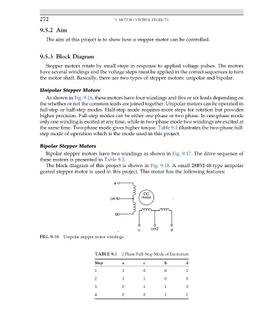
As shown in Fig. 9.16, these motors have four windings and five or six leads depending on
the whether or not the common leads are joined together. Unipolar motors can be operated in
full-step or half-step modes. Half-step mode requires more steps for rotation but provides
higher precision. Full-step modes can be either one phase or two phase. In one-phase mode
only one winding is excited at any time, while in two-phase mode two windings are excited at
the same time. Two-phase mode gives higher torque. Table 9.1 illustrates the two-phase full-
step mode of operation which is the mode used in this project.
Bipolar Stepper Motors
Bipolar stepper motors have two windings as shown in Fig. 9.17. The drive sequence of
these motors is presented in Table 9.2.
The block diagram of this project is shown in Fig. 9.18. A small 28BYJ-48-type unipolar
geared stepper motor is used in this project. This motor has the following features:
FIG. 9.16 Unipolar stepper motor windings.
TABLE 9.1 2 Phase Full-Step Mode of Excitation
Step a c b d
1 1 0 0 1
2 1 1 0 0
3 0 1 1 0
4 0 0 1 1