
Page 280 - ARM Based Microcontroller Projects Using MBED
P. 280
266 9. MOTOR CONTROL PROJECTS
A B C D Motor Rotation
0 0 0 0 Motor stopped
1 0 0 1 Clockwise
0 1 1 0 Anticlockwise
The A, B, C, D terminals of the H-Bridge are connected to GPIO port pins PC_0, PC_1,
PC_2, and PC_3 of the development board, respectively.
9.3.5 The PDL
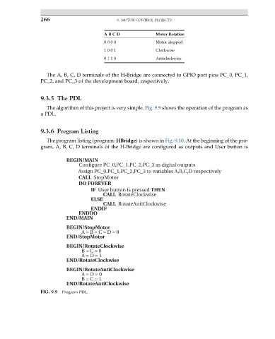
The algorithm of this project is very simple. Fig. 9.9 shows the operation of the program as
a PDL.
9.3.6 Program Listing
The program listing (program: HBridge) is shown in Fig. 9.10. At the beginning of the pro-
gram, A, B, C, D terminals of the H-Bridge are configured as outputs and User button is
BEGIN/MAIN
Configure PC_0,PC_1,PC_2,PC_3 as digital outputs
Assign PC_0,PC_1,PC_2,PC_3 to variables A,B,C,D respectively
CALL StopMotor
DO FOREVER
IF User button is pressed THEN
CALL RotateClockwise
ELSE
CALL RotateAntiClockwise
ENDIF
ENDDO
END/MAIN
BEGIN/StopMotor
A = B = C = D = 0
END/StopMotor
BEGIN/RotateClockwise
B = C = 0
A = D = 1
END/RotateClockwise
BEGIN/RotateAntiClockwise
A = D = 0
B = C = 1
END/RotateAntiClockwise
FIG. 9.9 Program PDL.