
Page 297 - ARM Based Microcontroller Projects Using MBED
P. 297
10.2 PROJECT 1—DISPLAYING TEXT ON THE LCD 283
Enable (E) is pin 6 which is used to initiate the transfer of commands or data between the
LCD module and the microcontroller. When writing to the display, data is transferred only on
the HIGH to LOW transition of this pin. When reading from the display, data becomes avail-
able after the LOW to HIGH transition of the enable pin and this data remains valid as long as
the enable pin is at logic HIGH.
Pins 7–14 are the eight data bus lines (D0–D7). Data can be transferred between the micro-
controller and the LCD module using either a single 8-bit byte, or as two 4-bit nibbles. In the
latter case only the upper four data lines (D4–D7) are used. The 4-bit mode has the advantage
that four less I/O lines are required to communicate with the LCD. The 4-bit mode is however
slower since the data is transferred in two stages. In this book we shall be using the 4-bit
interface only.
In 4-bit mode the following pins of the LCD are used. The R/W line is permanently
connected to ground. This mode uses six GPIO port pins of the microcontroller:
V SS ,V DD ,V EE ,E,R=S,D4,D5,D6,D7
10.2 PROJECT 1—DISPLAYING TEXT ON THE LCD
10.2.1 Description
In this project a 2 line by 16 character LCD is connected to the Nucleo-F411RE development
board. The text Nucleo-F411RE is displayed on the LCD.
10.2.2 Aim
The aim of this project is to show how text can be displayed on an LCD using Mbed with
the Nuclo-F411RE development board.
10.2.3 Block Diagram
The block diagram of the project is shown in Fig. 10.1.
10.2.4 Circuit Diagram
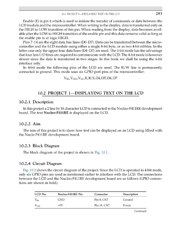
Fig. 10.2 shows the circuit diagram of the project. Since the LCD is operated in 4-bit mode,
only six GPIO pins are used as mentioned earlier to interface with the LCD. The connections
between the LCD and the Nucleo-F411RE development board are as follows (GPIO connec-
tions are shown in bold):
LCD Pin Nucleo-F411RE Pin Connector Description
V SS GND Pin 8, CN7 Ground
V DD +5V Pin 18, CN7 Power
Continued