
Page 302 - ARM Based Microcontroller Projects Using MBED
P. 302
288 10. USING LIQUID CRYSTAL DISPLAYS (LCDs)
FIG. 10.7 Program PDL.
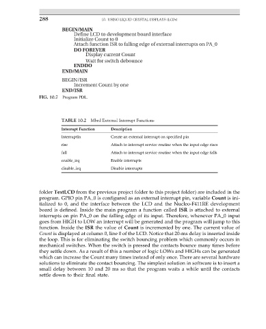
TABLE 10.2 Mbed External Interrupt Functions
Interrupt Function Description
InterruptIn Create an external interrupt on specified pin
rise Attach to interrupt service routine when the input edge rises
fall Attach to interrupt service routine when the input edge falls
enable_irq Enable interrupts
disable_irq Disable interrupts
folder TextLCD from the previous project folder to this project folder) are included in the
program. GPIO pin PA_0 is configured as an external interrupt pin, variable Count is ini-
tialized to 0, and the interface between the LCD and the Nucleo-F411RE development
board is defined. Inside the main program a function called ISR is attached to external
interrupts on pin PA_0 on the falling edge of its input. Therefore, whenever PA_0 input
goes from HIGH to LOW an interrupt will be generated and the program will jump to this
function. Inside the ISR the value of Count is incremented by one. The current value of
Count is displayed at column 0, line 0 of the LCD. Notice that 20-ms delay is inserted inside
the loop. This is for eliminating the switch bouncing problem which commonly occurs in
mechanical switches. When the switch is pressed the contacts bounce many times before
they settle down. As a result of this a number of logic LOWs and HIGHs can be generated
which can increase the Count many times instead of only once. There are several hardware
solutions to eliminate the contact bouncing. The simplest solution in software is to insert a
small delay between 10 and 20 ms so that the program waits a while until the contacts
settle down to their final state.