
Page 306 - ARM Based Microcontroller Projects Using MBED
P. 306
292 10. USING LIQUID CRYSTAL DISPLAYS (LCDs)
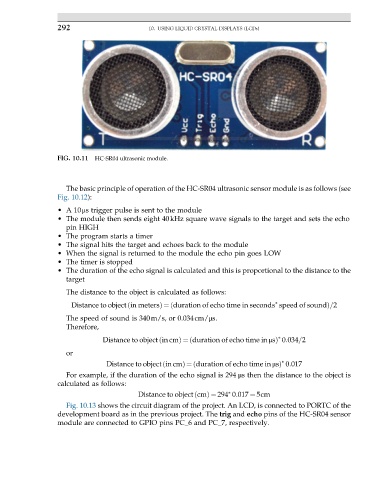
FIG. 10.11 HC-SR04 ultrasonic module.
The basic principle of operation of the HC-SR04 ultrasonic sensor module is as follows (see
Fig. 10.12):
•A 10μs trigger pulse is sent to the module
• The module then sends eight 40kHz square wave signals to the target and sets the echo
pin HIGH
• The program starts a timer
• The signal hits the target and echoes back to the module
• When the signal is returned to the module the echo pin goes LOW
• The timer is stopped
• The duration of the echo signal is calculated and this is proportional to the distance to the
target
The distance to the object is calculated as follows:
∗
Distance to object in metersÞ ¼ duration of echo time in seconds speed of soundð Þ=2
ð
The speed of sound is 340m/s, or 0.034cm/μs.
Therefore,
∗
Distance to object in cmÞ ¼ duration of echo time in μsÞ 0:034=2
ð
ð
or
∗
Distance to object in cmÞ ¼ duration of echo time in μsÞ 0:017
ð
ð
For example, if the duration of the echo signal is 294 μs then the distance to the object is
calculated as follows:
∗
Distance to object cmÞ ¼ 294 0:017 ¼ 5cm
ð
Fig. 10.13 shows the circuit diagram of the project. An LCD, is connected to PORTC of the
development board as in the previous project. The trig and echo pins of the HC-SR04 sensor
module are connected to GPIO pins PC_6 and PC_7, respectively.