
Page 305 - ARM Based Microcontroller Projects Using MBED
P. 305
10.4 PROJECT 3—ULTRASONIC HEIGHT MEASUREMENT 291
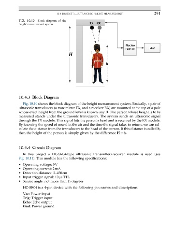
FIG. 10.10 Block diagram of the
height measurement system.
10.4.3 Block Diagram
Fig. 10.10 shows the block diagram of the height measurement system. Basically, a pair of
ultrasonic transducers (a transmitter TX, and a receiver RX) are mounted at the top of a pole
whose exact height from the ground level is known, say H. The person whose height is to be
measured stands under the ultrasonic transducers. The system sends an ultrasonic signal
through the TX module. This signal hits the person’s head and is received by the RX module.
By knowing the speed of sound in the air and the time the signal takes to return, we can cal-
culate the distance from the transducers to the head of the person. If this distance is called h,
then the height of the person is simply given by the difference H2h.
10.4.4 Circuit Diagram
In this project a HC-SR04-type ultrasonic transmitter/receiver module is used (see
Fig. 10.11). This module has the following specifications:
• Operating voltage: 5V
• Operating current: 2mA
• Detection distance: 2–450cm
• Input trigger signal: 10μs TTL
• Sensor angle: not more than 15degrees
HC-SR04 is a 4-pin device with the following pin names and descriptions:
Vcc: Power input
Trig: Trigger input
Echo: Echo output
Gnd: Power ground