
Page 340 - ARM Based Microcontroller Projects Using MBED
P. 340
326 13. UART PROJECTS
In serial connection a minimum of three lines are used for communication: transmit (TX),
receive (RX), and ground (GND). Two devices are used in serial communication: the trans-
mitter, and the receiver. The devices are connected such that the TX of one device is connected
to the RX of the other device, and its RX is connected to the TX. Some high-speed serial com-
munication systems use additional control signals for synchronization, such as CTS, DTR,
RTS, and so on. Some systems use software synchronization techniques where a special char-
acter (XOFF) is used to tell the sender to stop sending, and another character (XON) is used to
tell the sender to restart transmission. In this chapter we will be using low-speed communi-
cation and therefore the basic pins presented in Table 13.1 will be used with no hardware or
software synchronization.
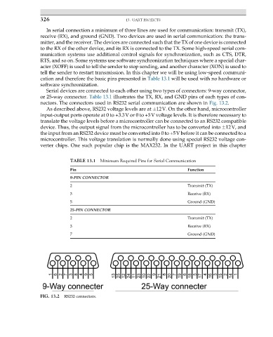
Serial devices are connected to each other using two types of connectors: 9-way connector,
or 25-way connector. Table 13.1 illustrates the TX, RX, and GND pins of each types of con-
nectors. The connectors used in RS232 serial communication are shown in Fig. 13.2.
As described above, RS232 voltage levels are at 12V. On the other hand, microcontroller
input-output ports operate at 0 to +3.3V or 0 to +5V voltage levels. It is therefore necessary to
translate the voltage levels before a microcontroller can be connected to an RS232 compatible
device. Thus, the output signal from the microcontroller has to be converted into 12V, and
the input from an RS232 device must be converted into 0 to +5V before it can be connected to a
microcontroller. This voltage translation is normally done using special RS232 voltage con-
verter chips. One such popular chip is the MAX232. In the UART project in this chapter
TABLE 13.1 Minimum Required Pins for Serial Communication
Pin Function
9-PIN CONNECTOR
2 Transmit (TX)
3 Receive (RX)
5 Ground (GND)
25-PIN CONNECTOR
2 Transmit (TX)
3 Receive (RX)
7 Ground (GND)
FIG. 13.2 RS232 connectors.