
Page 350 - ARM Based Microcontroller Projects Using MBED
P. 350
336 14. ADVANCED PROJECTS
of the power supply, while the three other LEDs are connected to three GPIO ports. Further
information about the Wi-Fi expansion board can be obtained from the following website:
https://www.st.com/en/evaluation-tools/stm32-nucleo-expansion-boards.html?
querycriteria¼productId¼SC1971
14.3.6 The 4-Channel Relay Board
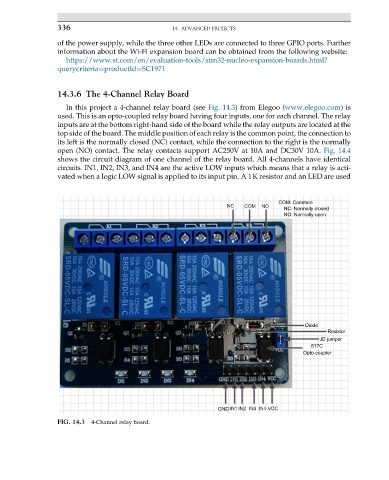
In this project a 4-channel relay board (see Fig. 14.3) from Elegoo (www.elegoo.com)is
used. This is an opto-coupled relay board having four inputs, one for each channel. The relay
inputs are at the bottom right-hand side of the board while the relay outputs are located at the
top side of the board. The middle position of each relay is the common point, the connection to
its left is the normally closed (NC) contact, while the connection to the right is the normally
open (NO) contact. The relay contacts support AC250V at 10A and DC30V 10A. Fig. 14.4
shows the circuit diagram of one channel of the relay board. All 4-channels have identical
circuits. IN1, IN2, IN3, and IN4 are the active LOW inputs which means that a relay is acti-
vated when a logic LOW signal is applied to its input pin. A 1K resistor and an LED are used
COM: Common
NC COM NO
NC: Normally closed
NO: Normally open
Diode
Resistor
JD jumper
817C
Opto-coupler
GND IN1 IN2 IN3 IN4 VCC
FIG. 14.3 4-Channel relay board.