
Page 407 - ARM Based Microcontroller Projects Using MBED
P. 407
16.3 PROJECT 1—HOME IoT PROJECT 393
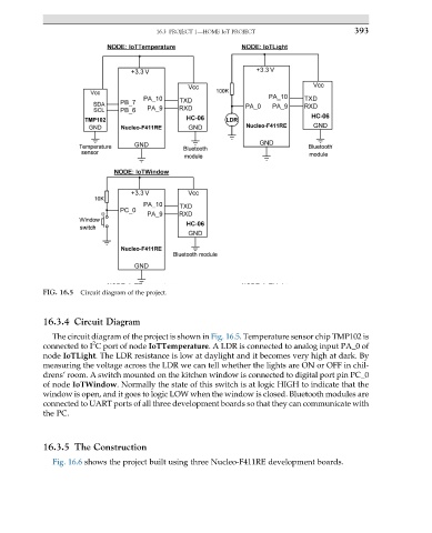
FIG. 16.5 Circuit diagram of the project.
16.3.4 Circuit Diagram
The circuit diagram of the project is shown in Fig. 16.5. Temperature sensor chip TMP102 is
2
connected to I C port of node IoTTemperature. A LDR is connected to analog input PA_0 of
node IoTLight. The LDR resistance is low at daylight and it becomes very high at dark. By
measuring the voltage across the LDR we can tell whether the lights are ON or OFF in chil-
drens’ room. A switch mounted on the kitchen window is connected to digital port pin PC_0
of node IoTWindow. Normally the state of this switch is at logic HIGH to indicate that the
window is open, and it goes to logic LOW when the window is closed. Bluetooth modules are
connected to UART ports of all three development boards so that they can communicate with
the PC.
16.3.5 The Construction
Fig. 16.6 shows the project built using three Nucleo-F411RE development boards.