
Page 411 - ARM Based Microcontroller Projects Using MBED
P. 411
16.3 PROJECT 1—HOME IoT PROJECT 397
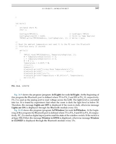
FIG. 16.8, CONT’D
Fig. 16.9 shows the program (program: IoTLight) for node IoTLight. At the beginning of
this program the Bluetooth port is defined where TX is PA_9 and RX is PA_10, respectively.
PA_0 is used as the analog port to read voltage across the LDR. The light level is converted
into lux. It is found by experiment that when the room is dark the light level is below 50.
Therefore, the message Lights are OFF is displayed if the room is dark, otherwise message
Lights are ON is displayed through the Bluetooth module every 15s.
Fig. 16.10 shows the program (program: IoTWindow) for node IoTWindow. At the begin-
ning of this program the Bluetooth port is defined where TX is PA_9 and RX is PA_10, respec-
tively. PC_0 is used as digital input port to read the state of the window switch. If the switch is
at logic HIGH then the message Window is OPEN is displayed, otherwise message Window
is CLOSED is displayed through the Bluetooth module every 15s.