
Page 88 - ARM Based Microcontroller Projects Using MBED
P. 88
74 6. ARCHITECTURE OF THE STM32F411RET6 MICROCONTROLLER
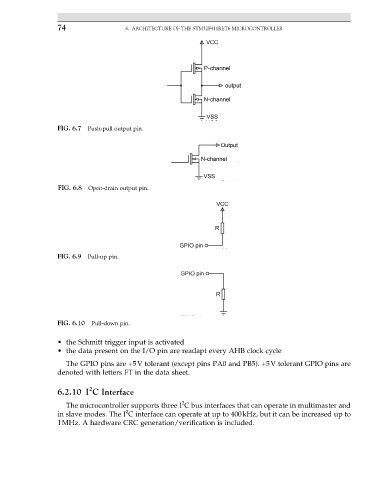
FIG. 6.7 Push-pull output pin.
FIG. 6.8 Open-drain output pin.
FIG. 6.9 Pull-up pin.
FIG. 6.10 Pull-down pin.
• the Schmitt trigger input is activated
• the data present on the I/O pin are readapt every AHB clock cycle
The GPIO pins are +5V tolerant (except pins PA0 and PB5). +5V tolerant GPIO pins are
denoted with letters FT in the data sheet.
2
6.2.10 I C Interface
2
The microcontroller supports three I C bus interfaces that can operate in multimaster and
2
in slave modes. The I C interface can operate at up to 400kHz, but it can be increased up to
1MHz. A hardware CRC generation/verification is included.