
Page 53 - Acquisition and Processing of Marine Seismic Data
P. 53
44 2. MARINE SEISMIC DATA ACQUISITION
acoustic devices, tail buoy storage and work- 2.1.2 Hydrophones and Streamer
shop, and a streamer repair room (Fig. 2.4D).
All of the seismic operations related to the data In land seismics, reflection signals are per-
recording, onboard processing, QC, navigation, ceived by geophones and transmitted to the
etc., are conducted from seismic instrument recorder following a conversion into electrical
room (Fig. 2.4E). Navigators and observers all signals. In marine seismics, reflection ampli-
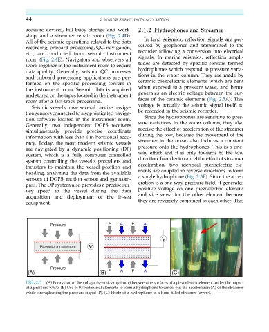
tudes are detected by specific sensors termed
work together in the instrument room to ensure
hydrophones which respond to pressure varia-
data quality. Generally, seismic QC processes
and onboard processing applications are per- tions in the water column. They are made by
formed on the specific processing servers in ceramic piezoelectric elements which are bent
the instrument room. Seismic data is acquired when exposed to a pressure wave, and hence
and stored on the tapes located in the instrument generates an electric voltage between the sur-
room after a fast-track processing. faces of the ceramic elements (Fig. 2.5A). This
Seismic vessels have several precise naviga- voltage is actually the seismic signal itself, to
be recorded in the seismic recorder.
tion sensors connected to a sophisticated naviga-
Since the hydrophones are sensitive to pres-
tion software located in the instrument room.
sure variations in the water column, they also
Generally, two independent DGPS receivers
receive the effect of acceleration of the streamer
simultaneously provide precise coordinate
during the tow, because the movement of the
information with less than 1 m horizontal accu-
streamer in the ocean also induces a constant
racy. Today, the most modern seismic vessels
pressure onto the hydrophones. This is a one-
are navigated by a dynamic positioning (DP)
way effect and it is only towards to the tow
system, which is a fully computer controlled
direction. In order to cancel the effect of streamer
system controlling the vessel’s propellers and
thrusters to maintain the vessel position and acceleration, two identical piezoelectric ele-
heading, analyzing the data from the available ments are coupled in reverse directions to form
sensors of DGPS, motion sensor and gyrocom- a single hydrophone (Fig. 2.5B). Since the accel-
pass. The DP system also provides a precise sur- eration is a one-way pressure field, it generates
vey speed to the vessel during the data positive voltage on one piezoelectric element
acquisition and deployment of the in-sea and vice versa for the other element because
they are reversely conjoined to each other. This
equipment.
FIG. 2.5 (A) Formation of the voltage (seismic amplitude) between the surfaces of a piezoelectric element under the impact
of a pressure wave. (B) Use of two identical elements to form a hydrophone to cancel out the acceleration (A) of the streamer
while strengthening the pressure signal (P). (C) Photo of a hydrophone in a fluid-filled streamer (arrow).