
Page 56 - Acquisition and Processing of Marine Seismic Data
P. 56
2.1 COMPONENTS OF MARINE SEISMIC ACQUISITION 47
FIG. 2.7 (A) A photo of a small part of the fluid-filled stretch section (transparent segment) and solid active sections
(opaque blue segments), and (B) sketch of the contents of a typical fluid-filled streamer section.
located one or two per section close to the end and up- and down-link data communication to
points, and strength members. The external and from the recorder in the instrument room.
jacket covering the whole exterior surface of Outputs of 8–16 adjacent hydrophones are
the streamer is commonly produced from grouped with an electrical connection in parallel
3 mm thick polyurethane, which protects the to form a single recording channel (Fig. 2.8)
hydrophones and wirings in the streamer sec- which enhances the low-frequency response of
tion from sea water intrusion. Each section has the hydrophone array. The hydrophone groups
typically two or three strength members extend- are formed by combining either equally or
ing from one end to another, which carry and unequally spaced hydrophones with equivalent
transmit the tension load along the streamer sensitivity. This is a similar configuration to the
due to the towing of the vessel. Each fluid-filled receiver arrays used in land seismics to attenu-
streamer section contains buoyancy spacers ate ground roll and enhance the reflection
located at regular intervals along the streamer amplitudes. By grouping the hydrophones,
cable, which ensures that the sections are of reflected signal amplitudes are enhanced since
the same average density as the surrounding they are all in-phase while out-of-phase random
ocean water to make the streamer neutrally noise is suppressed. Channels composed of only
buoyant when it is in the water. Inside the sec- one single hydrophone in fluid-filled streamers
tions, there is also a cable bundle extending are excessively noisy. Therefore, suitable design
along the whole streamer, which consists of nec- of the hydrophone groups may also attenuate
essary wirings for electrical power transmission the effect of bulge waves, and hence, reduce the
for streamer and digitizers as well as bird coils, mechanical cable noise amplitudes in fluid-filled
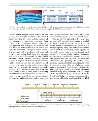
FIG. 2.8 Schematic sketch of hydrophone groups within the active streamer sections: Outputs of eight neighboring
hydrophones are grouped to form one recording channel.